Dry Valley Trough System Installation Guide
1. Introduction
1.1 TECHNICAL DATA
| Product: | C12 Dry Valley Trough – Aluminium C07 or C15 Valley Trim |
| Material: | Pre-primed Polyester coated Aluminium |
| Pitch Range: | 25° – 60° Degrees with a maximum difference between the two adjacent roofs of 20°. |
Roof area on plan draining into valley: Maximum 100m2
For maximum wind and rain resistance we recommend the use of a low modulus masc sealant at each overlap.
1.2 DESCRIPTION
Aluminium Valley Troughs are an excellent alternative to lead as they are more cost effective, tougher, and more resistant to accidental damage. The use of Aluminium Valley Troughs will significantly reduce installation me over traditional methods.
1.3 STORAGE
C12 Dry Valley Troughs should be stored on a raised platform, not resting on the ground, on a flat, clean, and level surface. Stack so as to avoid crushing or distorting the valley troughs.
2. Installation
2.1 GUIDANCE NOTES
Every site and project will be different but in general there are a number of important principles for the roofer.
The C12 Dry Valley Trough is a universal product which will work with concrete slates and les.
To ensure the product performs correctly over its lifetime it must be installed in the manner described below. NO deviation from the installation guide is recommended.
This installation guide is for roofs intersecting at 90°. For roof of any other intersection angle please contact our Technical department.
It is important when fixing the C12 Dry Valley Trough that the roof tiles/slates lie on a level plane and be installed in accordance with the manufacturer’s guide. Please ensure you follow Condron Concrete installation information and SR 82 recommendations to ensure the roof tiles/slates are nailed and/or clipped correctly.
2.2 DRY VALLEY TROUGH INSTALLATION
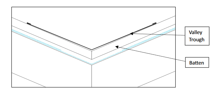
1. Due to its design, the C12 Dry Valley Trough does not require the cutting of timbers or the placement of any counter battens. The roof should be battened and underlay placed to the corner. The timberwork will be the same as if using a lead valley.
2. Some roofers apply a layer of DPC to where the Valley Trough will be fitted. This is not necessary but does provide an additional layer of protection.
3. The C12 Valley Trough comes preformed in a 135 degree internal angle. Using its malleable quality, the valley must first be dry fixed into the shape of the valley. This involves putting pressure manually on the pieces to bring the internal angle closer to the angle of the valley.

4.The first Valley Trough piece is placed at bottom with bottom edge protruding to match the finishing line of slates.
5.The Valley Trough can be installed using a nail or clip system.
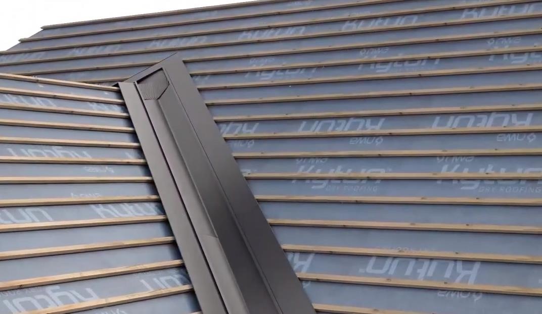
6. The first piece of valley trough is to be fixed at 600mm c/c at the outer most point straight through the valley trough on both sides using 40mm Galvanised Nail with rubber washer.

7. Repeat the laying process ensuring an overlap of 400mm minimum. A low modulus mastic sealant should be used to seal between the 2 Valley trough sections purely as a precaution.

Valley Trough installed.
8. As you reach the top of the Valley ensure the top piece has a minimum length of 1m. Cut to suit and butt the trough against the Trough from the other side. Using a lead alternative dress the intersection of the 2 valleys.
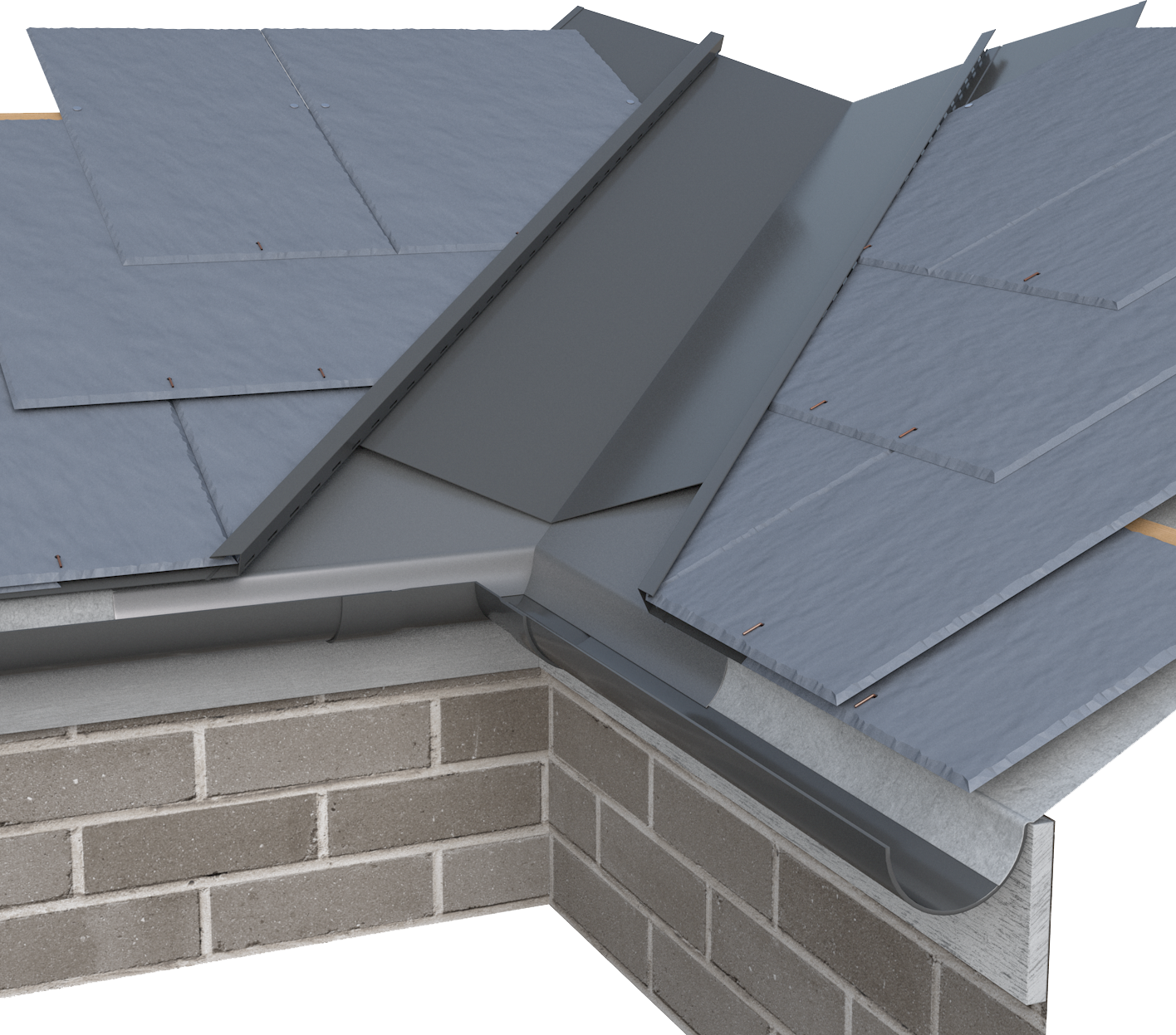
9. Next get your lengths of Tile or Slate Valley Trim onto the roof for installation. Beginnning at the boom overlay the trim onto the valley piece by a minimum of 100mm. Fix the trim through the flat portion into the battens 600mm c/c max using a 40mm Galvanised nail.
10. Sleeve the next piece into the previous by pressing gently on the metal. Continue to fix as per item no. 10
11. At the top of the valley, mitre the Valley trim to meet each other.

Valley Trough and Trim installed
12. Slate or tile as to manufacturers instructions.
Click here to download the C12 Dry Valley Installation Guide
