Structural Design
Structural Design
The forces acting on a cross section of pipeline arise from four main sources.
1. Weight of overlying fill.
2. Soil pressures transmitted to the pipe from surface loads i.e. traffic and other transient loads.
3. Supporting reaction below the pipe.
4. Water within the pipe (only significant for larger diameter pipes).
The four main conditions in which pipes are installed are:
1. In a ‘narrow’ trench.
2. In a ‘wide’ trench.
3. On the surface of ground over which an embankment is built.
4. In a narrow trench over which an embankment is built.
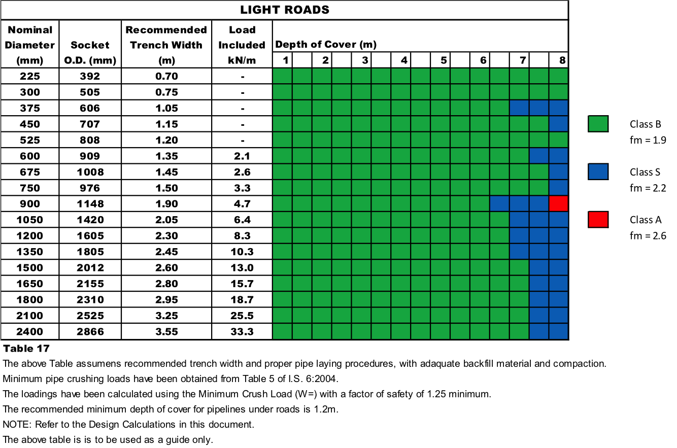
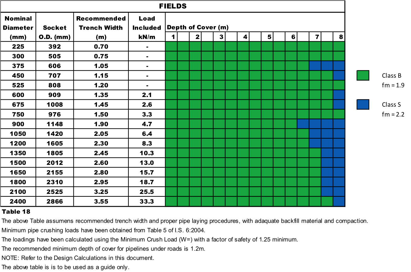
Design tables for condition 1 are supplied in the bedding Class / depth of cover tables. For conditions as stated in 2, 3 & 4 special design considerations apply and consultation may be required. It is structurally critical if trench width on site exceeds the designed trench width. Trench width should be inspected and recorded regularly. A trench adjacent to a manhole may need to be wider but this should be taken into account at design stage.
TESTING
The Irish Standard Specification for Concrete Sewer Pipes, I.S.6: 2004 gives minimum crushing test loads for each diameter of pipe. Loads are applied in a three edge-bearing test described in the standard. Hydraulic tests are also carried out, by applying an internal hydraulic pressure of 0.5 bar to test for porosity. We also employ a 100% gauging system of our Spigots and Sockets to ensure watertight joints to 10m head of water.
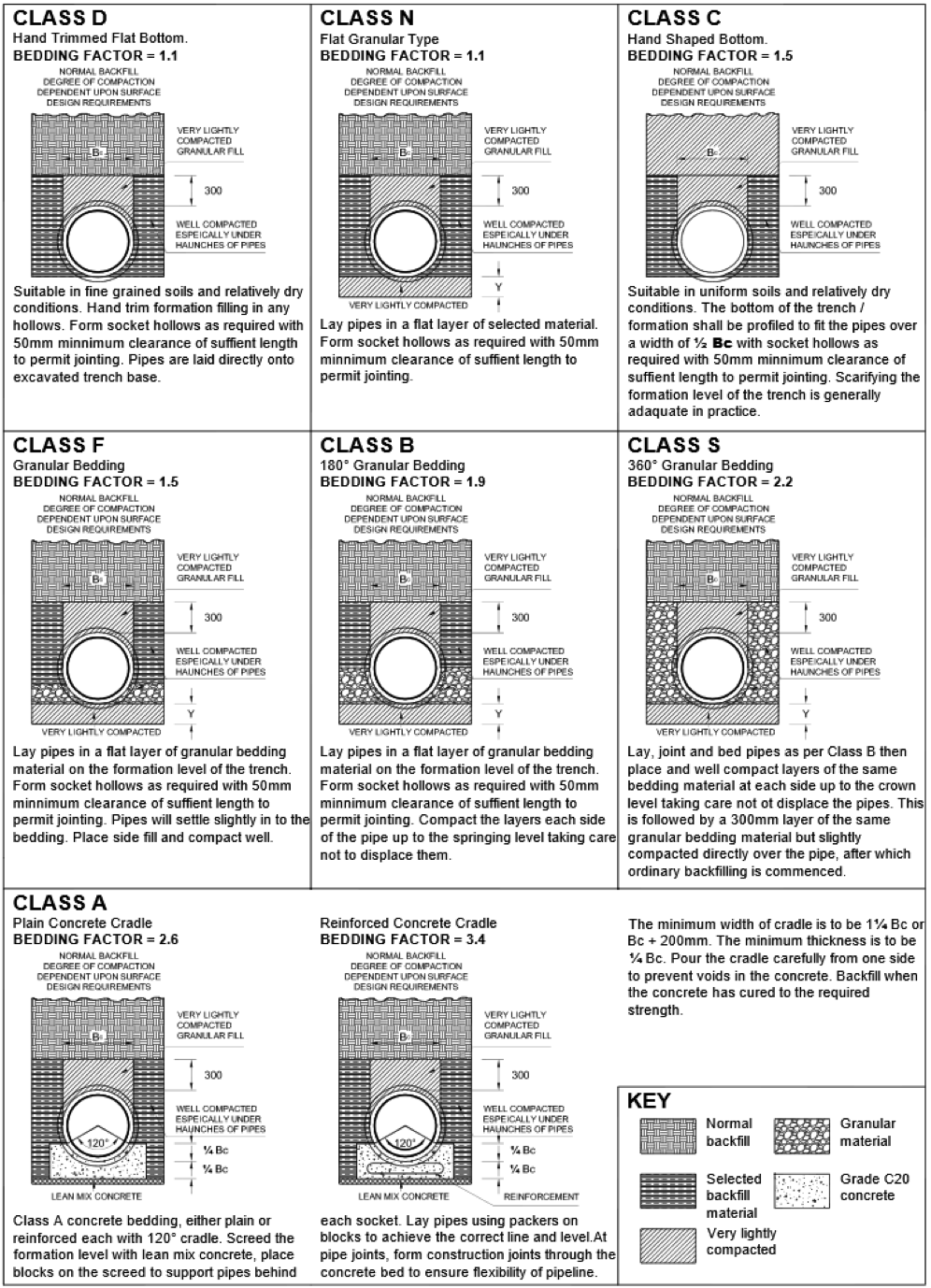
BEDDING FACTORS AND MATERIAL
In the three edge-bearing test, the vertical loading and supporting reactions are line loads. The strength of the pipes determined in the crushing test is multiplied by a bedding factor (Fm), which represents the amount by which the stresses in the pipe are reduced because of the spreading properties of the bedding for load and reaction.
The value of bedding factor (Fm) for a particular method of construction is not a precise figure but is affected by the quality of workmanship. The figures given are assuring a good standard of workmanship. Pipe settlement will be kept to a minimum by the proper selection and compaction of the bedding material. The bedding should be compacted to a density not less than that of the natural soil in the sides and bottom of the trench. The bedding material should be of a similar particle size to that in the trench sides. Where the ground is clay or silt, bedding material must consist of all-in gravels to prevent the trench from becoming a drainage channel and thus carrying away fines from the trench walls and bedding and causing settlement of the pipes. Rounded single size material is not recommended. The bedding directly beneath or above the pipeline must not be over compacted; otherwise line loading of the pipes will result. Research and long experience has shown the following rule of thumb to be acceptable with a maximum of 40mm and limit on fine sands.
| ↓ (mm) Pipe | Bedding Material Size |
| 225 – 600 | 5 – 14mm |
| 675 – 1500 | 15 – 20mm |
| 1650 – 2400 | 25 – 40mm |
COMPACTION
The degree of compaction shall be as specified in the structural design of the pipeline. Specified degrees of compaction shall be controlled by a method specification related to the particular equipment used (compaction means) or, where required, verified by testing.
The initial backfill directly above the pipe should be compacted by hand where required. Mechanical compaction of the main backfill directly above the pipe should not be commenced until there is a total depth of cover of least 300mm above the top of the pipe. The total depth of the cover directly above the pipe before mechanical compaction is commenced depends on the type of compaction device. The choice of compaction equipment, the number of passes and the thickness of layer to be compacted shall take account of the material to be compacted and the pipe to be installed.
Compaction by saturating the backfill or side fill is permissible only in exceptional cases and then only in suitable, non-cohesive soils.
MINIMUM DEPTH OF COVER
It is advisable that pipes laid under roads should have cover over the pipe of not less than 1.2m. Pipes laid with less than 1.2m cover require special consideration. For pipes laid in fields a minimum cover of 0.6m should be provided. At shallower depths there is a risk of damage from agricultural operations.
DESIGN CALCULATIONS
The required crushing strength of a concrete pipe can be calculated using the following equation.
Wt > (We x Fs) / Fm
Where: Wt = required I.S.6 crushing load (kn/m), (Fn=Wt)
We = Total applied load on the pipe (kn/m)
Fs = Factor of safety (1.25 MINIMUM)
Fm = the bedding factor
Crushing load (Wt) as stated in I.S. 6: 2004 “Perforated Pipes” Table
NOTE:
The minimum crushing load (Wt) is the load which the pipe will sustain without collapse. The proof load (Wp) is the load which reinforced pipes sustain without developing a crack exceeding 0.3mm in width over a length of 300mm.. The Design Loads used in Tables 16, 17 and 18 are calculated from the Marston’s Formula to collapse. (Fn=Wt)
DEPTH OF COVER TABLES
Depth of cover tables are provided for I.S. 6: 2004 Minimum Crush Strength and give a simple guide to maximum depth of cover for different bedding classes for single pipelines laid in a narrow trench. The density of fill is taken as 19.6kn/m³. This value is suitable for general design purposes and is unlikely to be exceeded in normal practice.
GENERAL
The general requirements of I.S. EN 1295 – 1: 1998 `Structural Design of Buried Pipelines’ must be followed. Under no circumstances should blocks or bricks be placed beneath pipes and special care should be taken with material immediately surrounding the pipeline to minimise the possibility of large size lumps of rock, hardcore etc. coming into direct contact with the pipe and thus causing point loading. With a Socketed pipe care must be taken to ensure that adequate clearance is given beneath the Socket. Uniform support along the pipeline is essential. Where pipes are installed in soft ground the thickness of the lower bedding may need to be increased to prevent excessive settlement of the pipeline.
FACTOR OF SAFETY
To allow for unexpected site conditions a minimum factor of safety of 1.25 should be allowed on the calculated external loads.
| Minimum Crush Test Loads I.S. 6: 2004 and ISEN 1916 | Minimum Crush Test Loads I.S. 6: 2004 and ISEN 1916 |
| Nominal Pipe (DN) | Minimum Crushing Load Fn kN/m (Fn=Wt) |
| 225mm | 27 |
| 300mm | 36 |
| 375mm | 45 |
| 450mm | 54 |
| 525mm | 63 |
| 600mm | 72 |
| 675mm | 81 |
| 750mm | 90 |
| 900mm | 108 |
| 1050mm | 126 |
| 1200mm | 144 |
| 1350mm | 162 |
| 1500mm | 180 |
| 1650mm | 198 |
| 1800mm | 216 |
| 2100mm | 252 |
| 2400mm | 288 |
Note 1, Sizes DN 225 to DN675 inclusive are manufactured unreinforced.
Note 2, Sizes DN 750 and above are manufactured reinforced.
Note 3, When using Condron Concrete I.S. 6: 2004 reinforced pipes the proof load is 80% of the minimum crushing load and the normal factor of safety of 1.25 is sufficient.
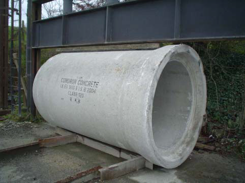
1200mm ø I.S. 6 Pipe undergoing Crush Test
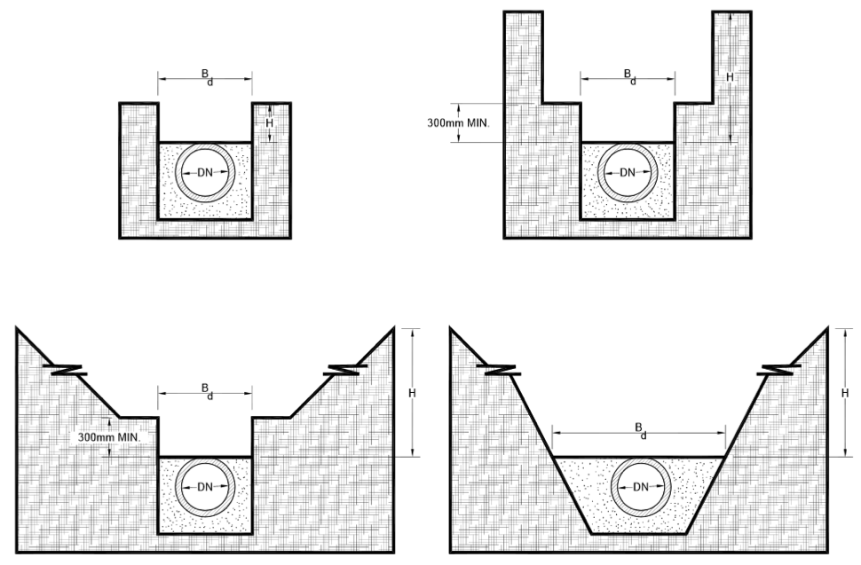
TRENCH WIDTHS
Narrow trench conditions – the assumed widths are given in the depth of cover charts.
The effective trench width (Bd)
FOR ISEN 1916 AND I.S. 6: 2004, CLASS 120 PIPES
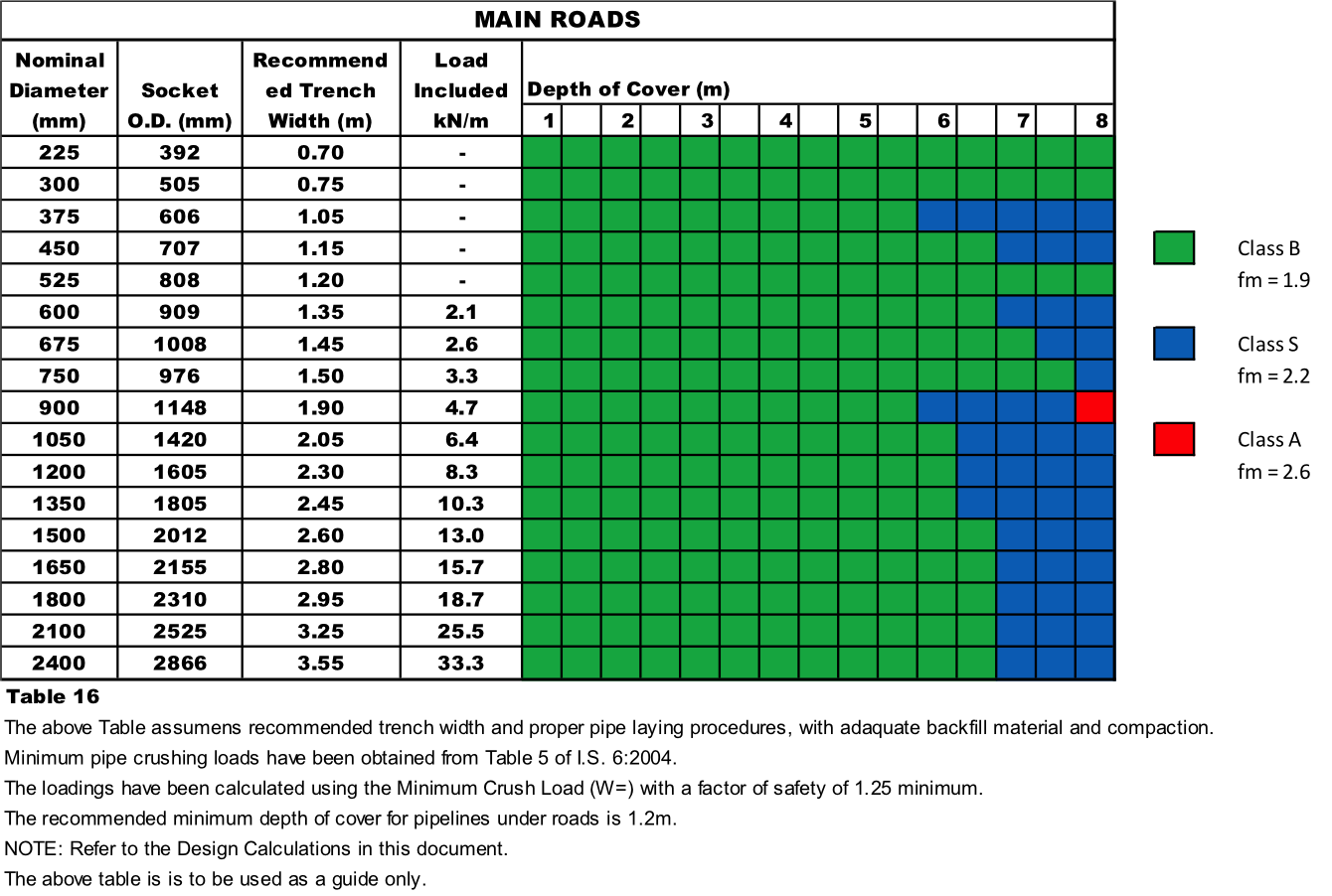
FOR ISEN 1916 AND I.S. 6: 2004, CLASS 120 PIPES
FOR ISEN 1916 AND I.S. 6: 2004, CLASS 120 PIPES
Would you like to talk to us about your requirements?
Download our Concrete brochure