Lamell Rubber Gasket
The newcomer, which gives your concrete pipe uplift
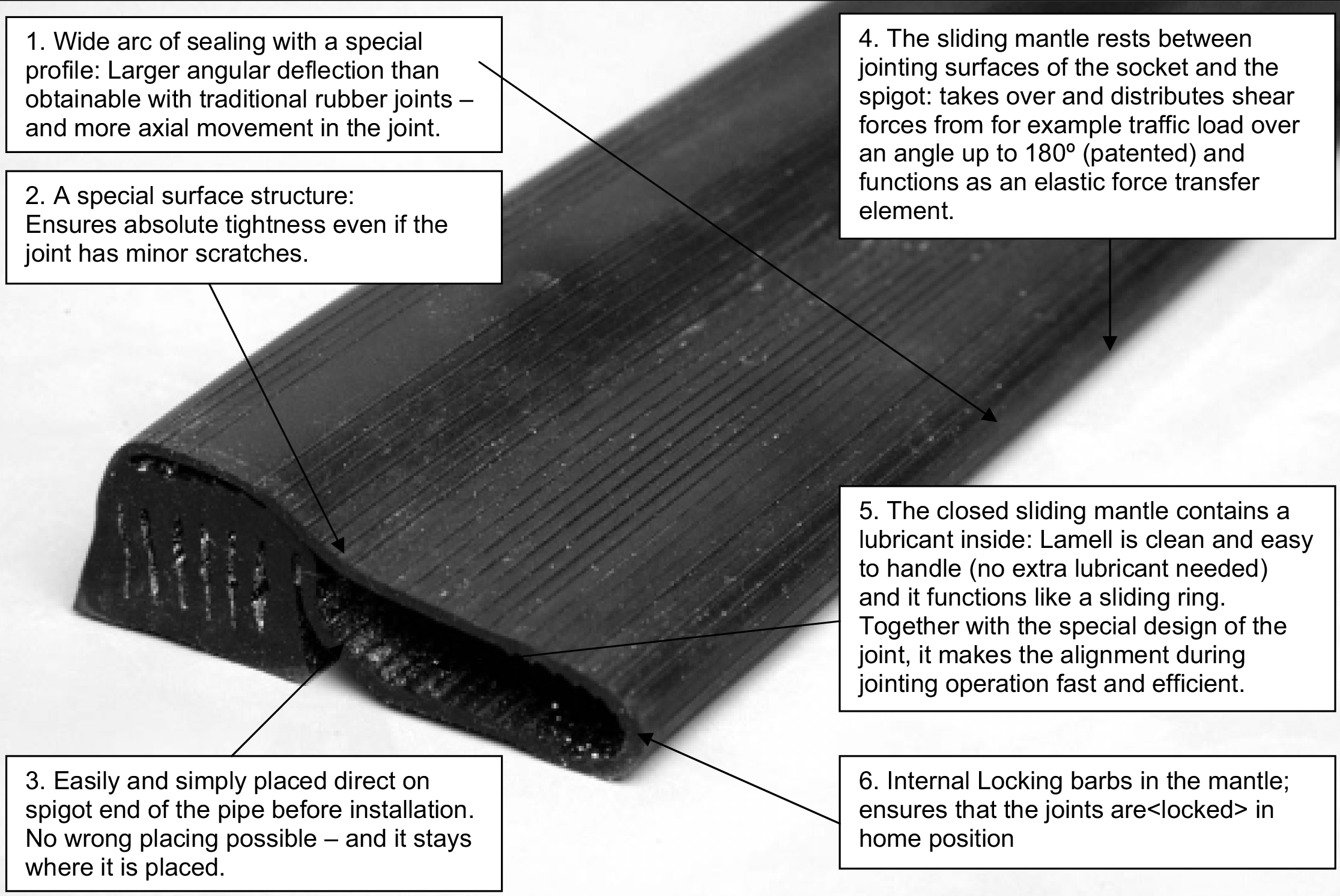
Today, it is normal to use either roll-in type or sliding ring joints on concrete pipes. Both of them have well-known advantages as well as disadvantages. But the demands for tightness and strength of pipe systems have been increased, however. The inventor of the brilliant Lamell system has considered this.
The Lamell joint has been developed in cooperation with contractors, concrete pipe manufacturers, and pipe machine producers. This ensures that the Lamell joint combines the advantages of all known types of joint without having their disadvantages.
Because of the design of the Lamell joint and the elasticity and the configuration of the Lamell gasket, the compression of the Lamell gasket will always be within the needed limits, as well as the tightening area will not change within the tolerance limits. This ensures an absolutely tight pipeline.
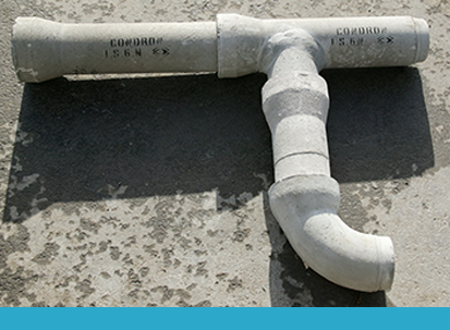
The Lamell joint can be used in connection with all known dimensions and shapes of pipes for sewer and low head pressure systems as well as for manhole systems.
The Lamell gasket is patented.
Because of the combined strength and elasticity of the Lamell gasket, and because the limited annular space between the concrete surfaces formed by the socket and spigot is occupied by the sliding mantle, the intrusion of root webs from plants and trees is prevented automatically.
Furthermore the joint is designed for automatic and mechanical installation of pipes in order to reduce the manual handling in the trench. The Lamell gasket meets for example the specifications of: D.S.421.2 – SS 367611 – B.S.I.2494 (2) – ASTM 443 – ASTN 505 – ISO/DIS 4633 – ASTM-361.
The Lamell gaskets are normally delivered in a SBR-rubber compound and are resistant to all substance normally found in ordinary drainage and sewer systems and are resistant to microbiological attacks from anaerobes.
Lamell gaskets can be delivered in an oil resistant Neoprene quality as well as in an EPDM-quality.
Please ask for more technical details if necessary.
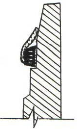
Spigot Type A (225, 300, 375, 450, 525, 750,900mm)
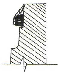
Spigot Type B (600, 675, 1050, 1200, 1350, 1500, 1800, 2100mm)
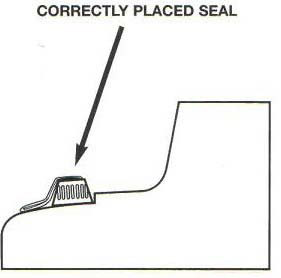
Spigot
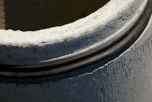
Spigot end of I.S. 6 Pipe
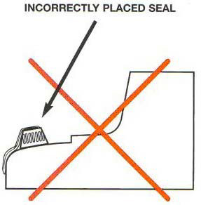
Incorrect Positioning of gasket

Gasket position prior to joint connection

Gasket position during joint connection

Gasket position after joint connection
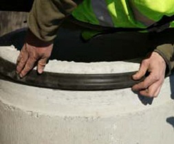
1. Ensure Spigot is clean. Position gasket as outlined on supplied illustration to suit Spigot Type A or B
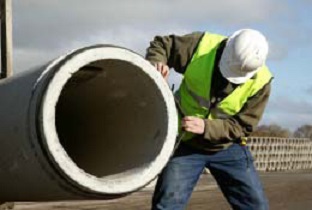
2. Check that gasket is equally tensioned around pipe B
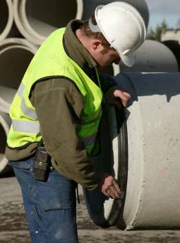
3. Ensure gasket is NOT protruding onto higher lip.
- Clean the Spigot and the Socket of the previous pipe with a damp cloth ensuring no debris will interfere with the joint
- Apply the gasket as illustrated for spigot type A or type B. No lubricant required.
- Check that the gasket is evenly tensioned all the way round.
- Finally check to ensure that the gasket has not protruded onto the higher lip of the Spigot.
- When jointing check for proper horizontal and vertical alignment of the two pipes so the gasket rolls correctly and neatly into position giving a watertight joint.
- Prior to the pipe being fitted into its final position all gaskets should be checked to ensure twisting has not occurred, particularly if the alignment of the pipe has been altered

